How to Wire the J4 Trouble Output Properly

Posted by Lee Dubé | About the Author on Apr 6, 2017 12:27:02 PM


The Purpose and Proper Use of the J4 Output

Today’s blog is not intended to be overly technical.  The intent is to raise awareness of the J4 output on subscriber units; it purpose and proper use.  J4 is the output connector for the Form C Fail Secure Antenna Cut / Acknowledge Delay Relay / Low Battery / Charger Fail located on the subscriber circuit board. The subscriber will engage this relay for normal operation. It will be disengaged for one or more of the following reasons:

  • antenna cut
  • communication troubles or Acknowledge Delays (Ack Delay)
  • low battery
  • charger fault
  • Loss of power
    • Loss of AC, Beginning with Rev 2.64ZI of 7788F and 7744F, disabled by default
      • Note: AC failure does not report from J4, except on 7788F/7744F Rev 2.64Zi + if enabled
  • A pushbutton, remote or watchdog reset which causes the routing table to be deleted, resulting in the Subscriber not being on the network

Read the Post >

Topics: Insider

How to Test RF Performance

Posted by Lee Dubé | About the Author on Feb 8, 2017 10:13:00 AM


Testing Your Cable Installation, Antenna & Transceivers Performance

In our last AES Insights Blog post, we reviewed the importance of selecting proper coaxial cable and its installation.  In today’s Blog, we’ll briefly review just a few ways you can test your cable installation along with your antenna and transceivers performance.

There are several points of failure associated with Radio Frequency (RF) power performance.  During the course of terminating coaxial cable, it’s possible to damage one or more of the cable components (such as the conductor, dielectric, shielding, etc.).  This type of damage will degrade performance of the network.  Other performance impacting areas include tight cable bends, cables damaged by weather conditions, damage to antennas, and underpowered transceivers to name a few.

Read the Post >

Topics: Insider

Coax Cable Selection and Termination

Posted by Lee Dubé | About the Author on Jan 17, 2017 12:03:17 PM


Selecting the Right Coaxial Cable

Performing a quality installation will ensure optimal performance of your AES-IntelliNet® mesh radio network.  Selecting the right coaxial cable and properly installing it is the foundation to a quality installation.  Selection, however, can be challenging for those not familiar with the many types of coaxial cable and connectors currently on the market.  In this Blog post, we’ll help take some of the ‘guess-work’ out of the equation.

Coaxial cable is used as a transmission line for radio frequency signals. Its application includes connecting transceivers to their antennas.  One advantage of coaxial over other types of radio transmission line is the protection of the signal from external electromagnetic interference.  This allows coaxial cable runs (not the antennas!) to be installed next to metal objects such as gutters without the power losses that occur in other types of transmission lines.

There are a variety of coaxial cable types available today, each with a specific application.  Typically, coaxial cable has an identifier of RG (Radio Guide) followed by a number and, in some cases, the letter U (Universal).  Another coaxial cable identifier is LMR.  Cables with this identifier are low loss cables intended for longer distances.  Cable impedance (resistance of the cable) used in an AES network must be 50 Ohms, use of cable that does not have a 50 Ohm impedance will lead to adverse performance issues on the network.  AES requires the use of RG-58, RG-8 (Belden equivalent of 9913), or LMR-400 cable.

Cable distance is an important consideration when selecting coaxial cable.  The cable length will determine the type of cable that should be used.  The maximum distance for RG-58 cable is 25’ from the subscriber to the antenna, including the lightning protector. The maximum distance on RG-8 is 75’.  LMR-400 can be used up to 125’, you will need the specific terminations for that cable.

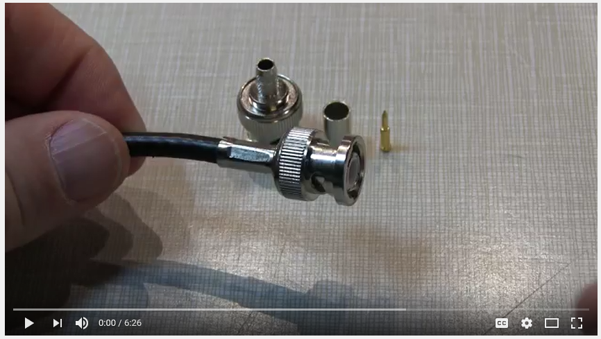
Proper cable terminations are vitally important to the performance of the network.  A bad crimp, loose connection, or damaged shielding will lead to signal loss, ground loops, signal degradation and much more.  To make installations easier, pre-terminated spools are available for purchase through AES in the following lengths: 10’, 15’, 20’ and 25’ (RG-58 is not in spools).  Spools of RG-8 with pre-terminated ends in lengths of 6’, 25’ and 50’ are available.  100’ spools of RG-8 with one end pre-terminated end are also available.

When terminating cable yourself, please keep the following items in mind:

Read the Post >

Topics: Insider

6 Steps for Performing a Quality Installation

Posted by Lee Dubé | About the Author on Aug 5, 2016 9:33:00 AM


Subscriber Installation

Performing a quality installation will ensure optimal performance of your AES-IntelliNet® mesh radio network. It will also provide the scalability necessary to rapidly grow your network and increase its resiliency. A comprehensive pre-installation AES Site Survey will equip the installer with valuable insight about the installation site. The site survey will reveal useful information such as:

  • Building construction information (whether the building is wood, concrete, metal, etc.)
  • Information about the distance from the Fire Alarm Control Panel (FACP), mounting location, etc. (this information is useful in estimating the amount of cabling, conduit, and wiring that will be necessary to complete the installation)
  • Network Connectivity (NetCon) at the site, meaning where in the building peak Radio Frequency (RF) performance be achieved.

Read the Post >

Topics: Insider

SUBSCRIBE TODAY!